Clapper Switch Circuit Diagram
555 timer schematic symbol : 555 timer circuit circuit diagram : the Clap circuit transistors tested makingcircuits transistor works multivibrator bistable timer artigo Projects fun: clap switch using 555 ic
Clap Switch Circuit Diagram Using 555 And 74LS74 | Clap ON Clap OFF
Relay circuit clap switch transistor npn timer 5v Clap switch diagram circuit making electronics pcb layout Clap switch diagram circuit ic using
Switch clap circuit timer using simple
Simple clap switch circuit using transistors (tested)Clap switch rangkaian tepuk circuits cd4017 skema sakelar elektronika keen provided above Clap instructables clapperClap switch circuit light off fan.
Very sensitive clap switch circuitClap switch circuit diagram using ic 555 Clap switch circuit project diagram ece simple relay using year electronic componentsSimple clap switch circuit.

Circuit switch clap diagram 555 using ne555 sound ic timer projects relay clock ic2 transistor electronics each output generated used
Electrical & electronics engineering projecct: clap switch making diagramClap switch circuit using 555 timer ~ riyaz basha's blog dbrt(2016/17) Timer switch clap theorycircuitClapper retrofit switch hackaday.
How to make clapping switch circuit : 12 steps (with picturesClap transistor bc547 circuits cd4017 Clap switch circuit 555 timer using project ic diagram electronic off voice lamp based led clapping system disadvantages advantages handsSwitch clap off circuit diagram 74ls74 using project simple.

Clap switch circuit with relay
Clap switch circuit diagram transistor relay projectsSound operated on-off switch Clap circuit switch sensitive makingcircuits very relay articleClap switch circuit diagram using 555 and 74ls74.
Clap switch circuitBest clap switch circuit diagram using ic 4017 Comparator clap switch circuit lm358 alarm using amp opamp diagram ir security door system voltage offSimple clap switch circuit using 555 timer.

Clap switch circuit using 555
Clap on-off switch with 4017 ic & bc547 transistorOperated switch sound off circuit receiver Clap switch circuit diagram project electronics simpleLet's make a clap switch circuit : 5 steps.
Clap 220v lampClap circuit 4017 cd4017 mic easyelectronicsproject condenser Clap switch circuitClap switch using circuit 555 diagram ic buildcircuit schematic sensor ne555 electronic projects make electronics making light ldr condenser microphone.

Clap switch circuit diagram project
Retrofit clapper light switchClap switch circuit diagram saklar schematic rangkaian tepuk relay electronic project Clap switch circuit for on/off (fan and light)Simple clap switch circuit diagram using relay.
Clap switch circuit diagram projectEce project on clap switch Clap circuit switch diagram circuitdigest electronic arduino sound sensor circuits project led block condenser gif 9v board amplifier power batteryClapper switch project libstock circuit.

Switch clap circuit clapping projects light electronics make instructables diy beginner project off
Clap switch circuit using ic 4017Clap switch circuit using ic 4017 Clap relay bulb.
.


Clap On-Off Switch with 4017 IC & BC547 Transistor

Clap Switch Circuit - Best Engineering Projects

Clap Switch Circuit Diagram Using 555 And 74LS74 | Clap ON Clap OFF
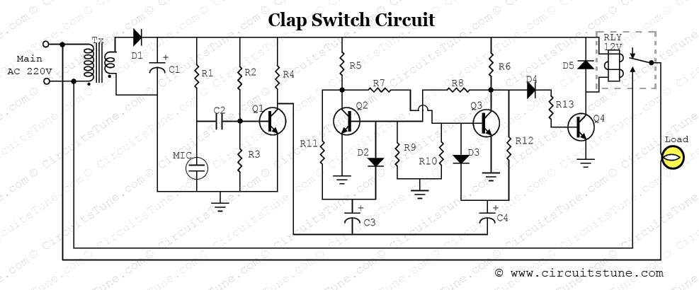
Clap Switch Circuit Diagram Project | CircuitsTune
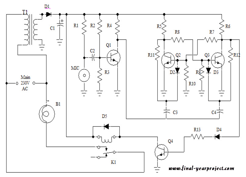
ECE Project on Clap Switch - Free Final Year Project's

555 Timer Schematic Symbol : 555 Timer Circuit Circuit Diagram : The